
Limit Switch Box: Open/Closed Position Feedback for Actuated Valves
Learn how limit switch boxes report the open and closed position of actuated valves to the control system, and how they are built, mounted and selected.
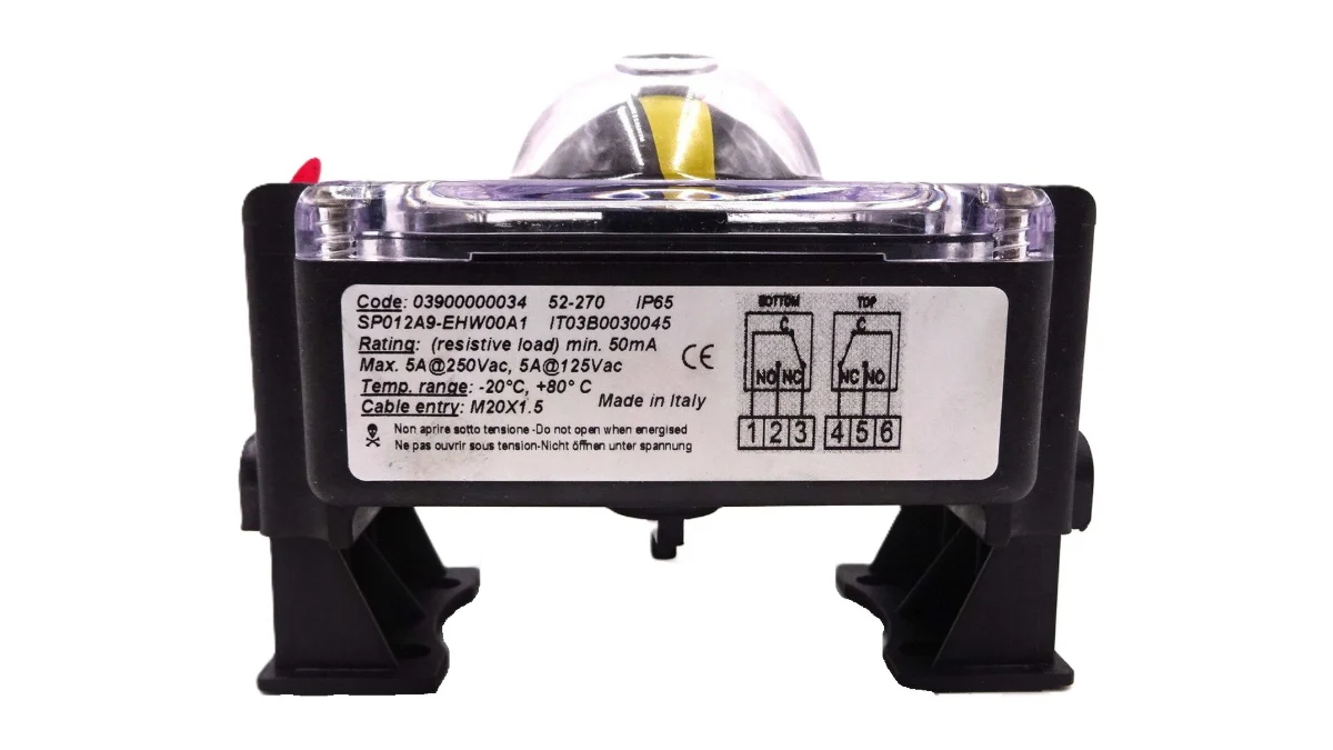
In a process with automated valves it is not enough for the control system to send an “open” command; it must also confirm that the valve has actually opened. A limit switch box is an accessory mounted on top of a pneumatic or electric actuator that detects the open and closed positions of the valve, sends this information as an electrical signal to the PLC or DCS and shows the position visually on site.
This article covers the design, working principle, technical features and selection points of limit switch boxes.
What Is a Limit Switch Box?
A limit switch box is a protective enclosure that usually contains two position switches. Its shaft is coupled to the actuator shaft and rotates with the valve. Adjustable cams on the shaft trip the switches when the valve reaches the open and closed positions, while a position indicator on top shows the valve status to the operator.
Working Principle
- Motion transfer: As the actuator turns the valve, the box shaft, coupled via the NAMUR interface, rotates through the same angle.
- Cam actuation: When the valve is fully open or fully closed, the relevant cam trips the switch opposite it.
- Contact change: The switch changes state (for example a normally open contact closes).
- Signal transmission: The contact status is wired to a control system such as a PLC or DCS.
- Action: The control system starts the next step, raises an alarm or detects that the valve has not reached the commanded position.
Technical Features
The table shows the construction of a typical limit switch box offered by ORFA. Values can vary by model.
| Feature | Typical value |
|---|---|
| Housing material | Die-cast aluminium |
| Position indicator | Transparent plastic dome with open/closed marking |
| Bolts | AISI 304 stainless steel |
| Seal | EPDM |
| Protection class | IP65 or IP67 depending on model |
| Actuator interface | NAMUR VDI/VDE 3845 |
| Switch type | Mechanical micro switch or inductive sensor |
Advantages
- Position confirmation: The control system knows the valve has reached the commanded position.
- Process safety: Valve jamming or actuator failure is detected quickly.
- Easy integration: The standard NAMUR interface allows mounting on different actuator brands with a bracket.
- Visual indication: Operators can see the valve status from a distance.
- Adjustability: Cams allow the switching points to be set precisely.
Applications
- Ball and butterfly valves with pneumatic or electric actuators
- Water and wastewater treatment plants
- Chemical, food and pharmaceutical processes
- Energy and steam systems
- Automated damper and flap systems
Selection Points
- Bracket and shaft adapter matching the actuator’s NAMUR dimensions
- Switch type suited to the control system input (mechanical contact, inductive sensor)
- Protection class and housing material for the ambient conditions
- Appropriately certified models for explosive atmospheres
- Additional switches or analogue position output if required
Frequently Asked Questions
Which actuators can a limit switch box be fitted to?
Quarter-turn (90°) pneumatic and electric actuators. Actuators with a NAMUR VDI/VDE 3845 interface accept it directly with a suitable bracket.
Mechanical switch or inductive sensor?
Mechanical micro switches are simple and economical. Inductive sensors work without contact and last longer on frequently cycling valves. Choose according to the control system input and cycle frequency.
How are the open/closed positions set?
With the cover removed, the cams on the shaft are turned and locked so that they trip the switches when the valve is fully open and fully closed.
Conclusion
A limit switch box reliably passes valve position information to the control system, keeping automated processes accurate and safe. Choosing the right switch type, protection class and mounting kit is the basis for long, trouble-free service. Explore more actuator accessories on our Actuator and Gear Operator Accessories page and contact the ORFA technical team for support.
Buy actuator accessories online
Browse products on or-fa.com, our export store, see prices in USD and order online.
Buy Online →Request a QuoteAsk on WhatsAppRelated product group
Actuator and Gear Operator Accessories →Technical support
Talk to our team to choose the right product.
+90 224 444 67 32[email protected]
Related Articles
Let’s choose the right product for your project
Buy from our online store or request a project-specific quotation.