
Centrifugal Pump Operating Point: System Curve, BEP and Hydraulic Calculation
An engineering look at the operating point where pump and system curves intersect, with a friction loss example, BEP, viscosity effects, affinity laws and series/parallel operation.
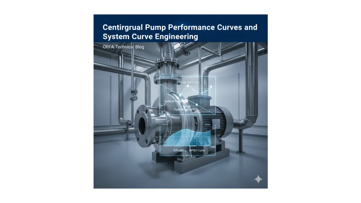
The flow and head figures in a centrifugal pump catalogue do not, on their own, tell you what the pump will actually do in your installation. The pump operates where its performance curve intersects the system curve of the pipework it is connected to. Determining the centrifugal pump operating point correctly is one of the most critical engineering steps for energy efficiency, cavitation control, bearing and seal life, and operating costs.
This article explains how to build a system curve, how to read pump curves, the consequences of a wrong operating point, a numerical friction loss example, the effect of viscosity, the affinity laws and series/parallel operation. For general selection criteria, see also our article on choosing the right pump.
Operating Point: Where Pump and System Curves Meet
The pump performance curve (Q–H) shows the head the pump can deliver at each flow rate. The system curve shows the head the installation requires at each flow rate:
Hsystem = Hstatic + Hlosses
The static head consists of the elevation difference between suction and discharge points and, where applicable, the pressure difference between the two vessels; it does not depend on flow. Pipe friction loss is calculated with the Darcy–Weisbach equation:
Hf = f × (L / D) × (V² / 2g)
Because losses increase with the square of velocity, and therefore of flow, the system curve is parabolic: losses grow rapidly as flow increases. Local losses in bends, valves and strainers are also proportional to velocity squared and must be added.
Reading Pump Curves
- Q–H curve: Relationship between flow and head.
- Q–P curve: Shaft power versus flow; the basis for motor sizing.
- Q–η curve: Efficiency curve; its peak is the best efficiency point (BEP).
- Q–NPSHr curve: NPSH the pump needs to run without cavitation; increases with flow.
In a good selection the operating point is as close as possible to the BEP. In practice the aim is to keep it roughly within 70–120% of BEP flow; the exact limits are set by the manufacturer’s recommended operating range.
Consequences of a Wrong Operating Point
| Condition | Possible consequences |
|---|---|
| Right of BEP (high flow) | Head drops, NPSHr rises and cavitation risk increases; in radial-flow pumps power rises and the motor may be overloaded. |
| Left of BEP (low flow) | Internal recirculation, higher radial loads and vibration, heating of the liquid; shorter bearing and mechanical seal life. |
| Any point far from BEP | Lower efficiency, higher energy costs, shorter maintenance intervals. |
Hydraulic Calculation Example
| Parameter | Value |
|---|---|
| Flow (Q) | 30 m³/h (0.00833 m³/s) |
| Pipe length (L) | 120 m |
| Pipe inner diameter (D) | 65 mm |
| Friction factor (f) | 0.024 |
| Static head | 12 m |
- Cross-section: A = π × 0.065² / 4 ≈ 0.00332 m²
- Velocity: V = Q / A ≈ 0.00833 / 0.00332 ≈ 2.5 m/s
- Velocity head: V² / 2g ≈ 2.51² / 19.62 ≈ 0.32 m
- Friction loss: Hf = 0.024 × (120 / 0.065) × 0.32 ≈ 14.2 m
- System head: Hsystem ≈ 12 + 14.2 ≈ 26.2 m
For this installation, choose a pump whose Q–H curve passes through about 26 m at 30 m³/h (slightly more once local losses are added) and which operates close to its BEP at that point.
The example also shows the importance of pipe size: assuming the same friction factor, an 80 mm inner-diameter pipe reduces velocity to about 1.7 m/s and friction loss to about 5 m. A larger pipe costs more to install but permanently reduces pump power and operating costs.
Correction for Viscous Liquids
Pump curves are published for water. When oils, glycol solutions or viscous chemicals are pumped, internal friction increases: head and flow fall, efficiency drops noticeably and power demand rises. The size of the effect depends on the liquid viscosity and the pump size. Water curves must therefore be corrected with recognised methods such as ANSI/HI 9.6.7, and the motor must be sized on the corrected values.
Affinity Laws and Adjusting the Operating Point
When the speed of the same pump changes, approximately:
- Flow changes in proportion to speed (Q ∝ n)
- Head changes with the square of speed (H ∝ n²)
- Power changes with the cube of speed (P ∝ n³)
This is why speed control with a frequency inverter is far more energy-efficient than throttling a discharge valve in variable-flow systems. For a pump that permanently produces too much head, trimming the impeller to the manufacturer’s recommendation is another option.
Pumps in Series and in Parallel
- Series: Heads add up at the same flow; used where high pressure is required or the static head is large.
- Parallel: Flows add up at the same head; used for high or variable flow demand. Because the system curve rises with flow, however, two pumps together deliver less than twice the flow of one pump.
In both cases, overlay the combined curve on the system curve to find the real operating point and check that each pump stays within its own operating range.
Frequently Asked Questions
How is the operating point of a centrifugal pump determined?
Plot the pump’s Q–H curve and the system curve on the same chart; their intersection is the operating point. The system curve is the static head plus friction and local losses, which rise with the square of flow.
What is BEP and why does it matter?
BEP is the flow at which the pump reaches its highest efficiency. Near this point energy consumption, vibration and radial loads are lowest, which extends bearing and seal life.
Do two pumps in parallel double the flow?
No. Flow increases, but since system losses rise with the square of flow, the combined flow is usually less than twice that of a single pump.
Throttling or speed control?
Throttling steepens the system curve to reduce flow, but the energy is lost in the valve. With speed control, power falls with the cube of speed, so an inverter is usually much more efficient in variable-flow systems.
Conclusion
The operating point of a centrifugal pump is the intersection of the pump and system curves, and it directly determines energy use, reliability and maintenance cost. A realistic system curve, selection close to BEP, NPSH and viscosity checks and correct speed control are the basis of long and efficient pump operation. Browse our centrifugal pumps page for suitable models, or ask the ORFA sales team for help with operating point calculations.
Buy centrifugal pumps online
Browse products on or-fa.com, our export store, see prices in USD and order online.
Buy Online →Request a QuoteAsk on WhatsAppRelated product group
Centrifugal Pumps →Technical support
Talk to our team to choose the right product.
+90 224 444 67 32[email protected]
Related Articles
Let’s choose the right product for your project
Buy from our online store or request a project-specific quotation.