
Pressure Reducing Valves
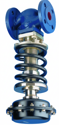
The pressure reducing valves in this group are used on steam, compressed air and neutral gas lines; they reduce a high and fluctuating inlet pressure to a constant, set outlet pressure on the line feeding the consumer. Threaded direct-acting bellows types are available for small consumers and flanged types for main distribution lines.
In direct-acting bellows types the outlet pressure is balanced on the bellows against a setting spring; setting is made with the adjusting handwheel in three spring ranges between 0.14 and 8.6 bar, and the valve body contains a stainless strainer. They are preferred where precise setting is not required, on 1/2″–1″ supplies to heaters, presses, irons and small process equipment.
Main Applications
- Steam irons, presses and small heater supplies
- Laboratory and kitchen steam equipment
- Pressure limiting at compressed air points of use
- Low-pressure steam branches leaving the boiler room
- Pressure reduction on neutral gas lines
Technical Data
| Operating principle | Direct acting; bellows and setting spring (threaded type) |
|---|---|
| Connection (threaded) | 1/2″, 3/4″, 1″ BSP or NPT |
| Body pressure class | PN25 |
| Max. inlet pressure | 19 bar |
| Max. outlet pressure | 8.6 bar |
| Setting ranges | 0.14–1.70 · 1.40–4.00 · 3.50–8.60 bar |
| Max. temperature | 210 °C |
| Recommended max. reduction ratio | 10:1 (at max. flow) |
| Dimensions (threaded) | Height 186.5 mm · length 83 / 96 / 108 mm (1/2″ / 3/4″ / 1″) |
| Installation | Horizontal line, following the arrow on the body |
| Flanged types | DN15–DN150, PN16–PN40, EN 558 Series 1 length, EN 1092 flanges |
| Flanged type tightness | Class I (DIN EN 1349; ≤ 0.05% of Kvs) |
Material Options
| Part | PN25 · ductile iron, threaded direct acting | PN16 · grey iron, flanged | PN40 · cast steel, flanged |
|---|---|---|---|
| Body | Ductile iron GGG40.3 | Grey iron EN-GJL-250 | Cast steel GP240GH+N (1.0619+N) |
| Seat | Stainless AISI 431 | Stainless 1.4021+QT | Stainless 1.4021+QT |
| Plug / valve | Stainless AISI 420 | Stainless 1.4021+QT, hardened | Stainless 1.4021+QT, hardened |
| Bellows | Stainless AISI 316 | Stainless bellows unit (depending on model) | Stainless bellows unit (depending on model) |
| Setting spring | Stainless steel | 51CrV4 (1.8159) | 51CrV4 (1.8159) |
| Strainer | Stainless AISI 316 | — | — |
| Bonnet gasket | Graphite | Pure graphite (CrNi laminated) | Pure graphite (CrNi laminated) |
| Bonnet | Aluminium upper cover | Ductile iron EN-GJS-400-18U-LT | Ductile iron EN-GJS-400-18U-LT |
Which type? On lines of 1″ and below, where precise outlet pressure setting is not required, the threaded direct-acting type is the economical solution; inlet pressure must not exceed 19 bar and outlet 8.6 bar. On high-flow main lines and for precise pressure setting, flanged diaphragm-actuated types are selected. Placing a steam separator ahead of the valve to remove moisture extends plug life.
Advantages
No Auxiliary Energy
- Works with line pressure and spring force.
- No electricity or compressed air needed.
Built-in Strainer
- Stainless strainer inside the body.
- Protects the seat from dirt and weld debris.
Three Setting Ranges
- From 0.14 up to 8.6 bar.
- The spring is chosen to suit the consumer pressure.
Compact Body
- 83–108 mm length, 186.5 mm height.
- Fits in a small space next to equipment.
Stainless Internals
- Bellows, plug and seat in stainless steel.
- Long life in steam and humid air.
Construction and Design Features
- Threaded ductile iron body and aluminium upper cover
- Stainless bellows sensing the outlet pressure
- Adjusting handwheel and setting stem with lock pin
- AISI 420 plug and AISI 431 seat
- Graphite bonnet gasket and stainless strainer inside the body
Send the inlet and required outlet pressure, the flow (kg/h or Nm³/h) and the connection size through the Request a Quote form; we will determine the right size and spring range from the capacity chart.
How to Choose?
- Define the pressuresNote the maximum inlet and required outlet pressure; the ratio should not exceed 10:1.
- Calculate the flowDetermine the steam (kg/h) or air demand of the consumer.
- Pick the size from the chartRead the size at the point where the outlet pressure meets the inlet curve on the capacity chart.
- Choose the spring rangeSelect the spring range that covers the outlet pressure.
- Plan the installationOn a horizontal line, fit an isolating valve and condensate drain upstream and a pressure gauge and safety valve downstream.
Complementary Products
Why ORFA?
Other Pressure Control Valves
Gas Pressure Reducing Regulators
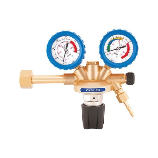
Gas pressure reducing regulators reduce and stabilize gas pressure in natural gas and LPG lines to the value required by the appliance.
Details →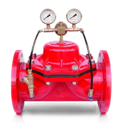
Hydraulic Pressure Reducing Control Valves
Hydraulic pressure reducing control valves stabilize outlet pressure in mains and large lines by means of a pilot circuit driven by line pressure.
Details →
Automatic Boiler Fill Valves
Automatic boiler fill valves automatically top up water when the pressure of a closed heating system drops.
Details →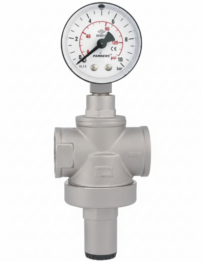
Water Pressure Reducing Valves
Water pressure reducing valves lower high mains pressure to a safe level for installations and appliances.
Details →Our Pressure Reducing Valves
ORFA supplies pressure reducing valves in a range of pressure classes, sizes and connection types to suit your application. Descriptions, technical specifications, materials and dimension tables are available on each detail page.
Get a quote for your project
Our sales team will prepare the best solution for your needs.