
Water Pressure Reducing Valves
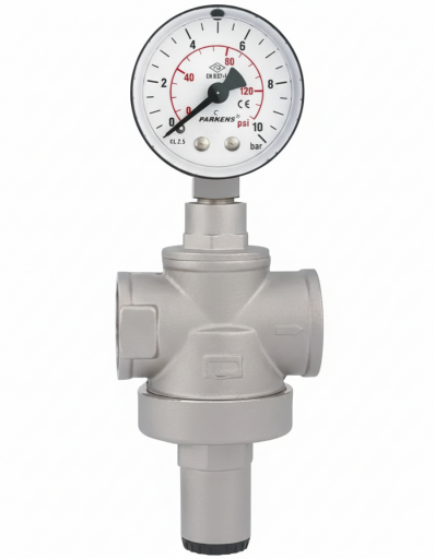
Water pressure reducing valves are brass-bodied, threaded plumbing fittings that reduce high or variable mains pressure to a constant value that will not damage the building installation. They protect taps, mixers, appliances and installation components from overpressure.
The piston design includes a compensation chamber that prevents changes in inlet pressure from affecting the outlet pressure. The valves comply with EN 1567 and are made in pressure class PN25 from 1/2″ to 4″; they are factory set to 3 bar, the outlet pressure can be adjusted between 0.5 and 7 bar depending on size, and a gauge fits into the two 1/4″ ports on the body.
Main Applications
- Water entries of homes, estates and office buildings
- Pressure limiting per floor and apartment
- Heating installation feed lines
- Process and service water in industrial plants
- Irrigation and garden line entries
Technical Data
| Standard | EN 1567 |
|---|---|
| Pressure class | PN25 (max. recommended working pressure 25 bar) |
| Setting range | 0.5–6 bar (1/2″–3/4″) · 1–6 bar (1″–2″) · 1–7 bar (2 1/2″–4″) |
| Factory setting | 3 bar |
| Temperature | 0 / +120 °C (frost excluded) |
| Connection | Female thread ISO 228/1, 1/2″ … 4″ |
| Gauge connection | Two 1/4″ G ports on the body |
| Operating principle | Piston type with compensation chamber |
| Seat | Stainless steel |
| Inlet–outlet difference | Inlet pressure must be at least 1 bar above the set outlet |
| Length (A) | 70 mm (1/2″) · 90 (1″) · 119 (2″) · 163 (3″) · 180 mm (4″) |
| Installation | Horizontal or vertical; not upside down |
Material Options
| Part | PN25 · brass body, 1/2″–2″ | PN25 · cast brass body, 2 1/2″–3″ |
|---|---|---|
| Body | Brass CW617N | Cast brass CB753S |
| Cap and spring housing | Brass CW617N | Brass CW617N |
| Stem | Brass CW614N (up to 1″) · AISI 304 (1 1/4″ and above) | Stainless AISI 304 |
| Disc, lock nut, valve | Brass CW614N | Brass CW614N |
| Seat | Stainless steel | Stainless steel |
| Setting spring | Steel C72 | Steel C72 |
| O-rings and seals | EPDM | EPDM |
Installation note: A strainer must be fitted ahead of the valve, with isolating valves before and after it; on lines with a water hammer risk, a hammer arrestor is used. For installations close to a boiler, an expansion vessel should be added so that thermal expansion pressure is not reflected back onto the valve.
Advantages
Balanced Outlet
- The compensation chamber damps inlet fluctuations.
- Constant pressure and flow at the taps.
Stainless Seat
- The face the valve closes on is stainless steel.
- More wear resistant than a brass seat.
Easy Setting
- Set on site with the screw under the cap.
- Checked through the gauge ports.
Wide Size Range
- One family from 1/2″ to 4″.
- From apartment entry to building main.
Standards Compliant
- Performance tests to EN 1567.
- Tightness and setting deviation verified.
Construction and Design Features
- Brass body and piston with compensation chamber
- Stainless seat and EPDM sealing elements
- C72 steel setting spring and brass adjusting cap
- Two 1/4″ gauge ports
- Flow direction arrow on the body
Send the inlet pressure, required outlet pressure, pipe size and place of use through the Request a Quote form; we will prepare a pressure reducer with the right size and setting range.
How to Choose?
- Measure mains pressureDetermine the highest inlet pressure with a gauge.
- Choose the outlet valueSet the outlet pressure to suit the installation; the inlet must be at least 1 bar higher.
- Determine the sizeSelect the size from pipe size and flow, also considering pressure loss.
- Check the setting rangeConfirm that the setting range of the chosen size covers the required outlet.
- Install correctlyFit a strainer and isolating valve upstream and connect following the arrow, not upside down.
Complementary Products
Why ORFA?
Other Pressure Control Valves
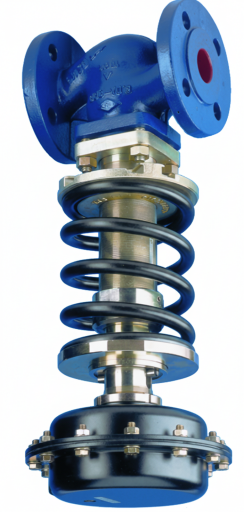
Pressure Reducing Valves
Pressure reducing valves keep the set outlet pressure constant even when the inlet pressure changes.
Details →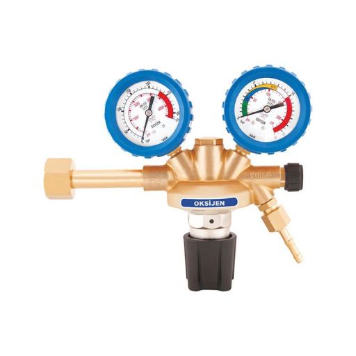
Gas Pressure Reducing Regulators
Gas pressure reducing regulators reduce and stabilize gas pressure in natural gas and LPG lines to the value required by the appliance.
Details →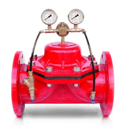
Hydraulic Pressure Reducing Control Valves
Hydraulic pressure reducing control valves stabilize outlet pressure in mains and large lines by means of a pilot circuit driven by line pressure.
Details →
Automatic Boiler Fill Valves
Automatic boiler fill valves automatically top up water when the pressure of a closed heating system drops.
Details →Our Water Pressure Reducing Valves
ORFA supplies water pressure reducing valves in a range of pressure classes, sizes and connection types to suit your application. Descriptions, technical specifications, materials and dimension tables are available on each detail page.
Threaded Water Pressure Reducing Valve
Threaded water pressure reducing valve: piston or diaphragm, brass body, 1/2″–2″, max. 25 bar inlet, setting 1–6 bar, with gauge and fitting options.
Details →Flanged Water Pressure Reducing Valve
Flanged water pressure reducing valve: GGG40 ductile iron body, DN50–DN200, PN16, adjustable outlet pressure. For building main entrances, fire and mains lines.
Details →Get a quote for your project
Our sales team will prepare the best solution for your needs.